This is a list of notable 8-bit computer color palettes, and graphics, which were primarily manufactured from 1975 to 1985. Although some of them use RGB palettes, more commonly they have 4, 16 or more color palettes that are not bit nor level combinations of RGB primaries, but fixed ROM/circuitry colors selected by the manufacturer. Due to mixed-bit architectures, the n-bit distinction is not always a strict categorization. Another error is assuming that a computer's color palette represents what it can show all at once. Resolution is also a crucial aspect when criticizing an 8-bit computer, as many offer different modes with different amounts of colors on screen, and different resolutions, with the intent of trading off resolution for color, and vice versa.
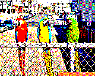
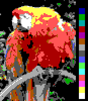
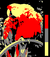
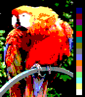
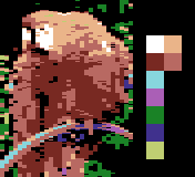
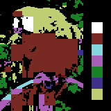
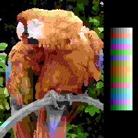
Sample image
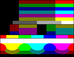
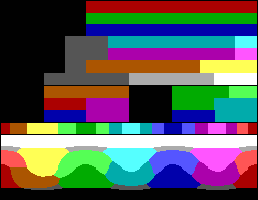
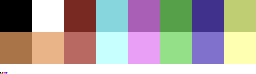
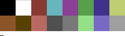
Color test chart
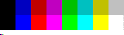
3-bit, 8-color palette
6-bit, 64-color palette
3-bit RGB palettes
Systems with a 3-bit RGB palette use 1 bit for each of the red, green and blue color components. That is, each component is either "on" or "off" with no intermediate states. This results in an 8-color palette ((21)3 == 23 == 8) that have black, white, the three RGB primary colors red, green and blue and their correspondent complementary colors cyan, magenta and yellow as follows:
Sample image
Palette coverage
Color indexes
The color indices vary between implementations; therefore, index numbers are not given. A common selection has 3 bits (from LSB to MSB) directly representing the 'Red', 'Green' and 'Blue' (RGB) components in a number from 0 to 7. An alternate arrangement uses the bit order 'Blue', 'Red', 'Green' (BRG), such that the resultant palette - in numerical order - represents an increasing level of intensity on a monochrome display.
The 3-bit RGB palette is used by:
The ECMA-48 standard for text terminals (sometimes known as the "ANSI standard", although ANSI X3.64 does not define colors)
Teletext Level 1/1.5 Teletext.
Videotex
Oric computers
BBC Micro
The original NEC PC-8801 up to the MkII
The original NEC PC-9801 with original 8086 CPU before the VM/VX models
All Sharp X1 models before the X1 Turbo Z
The Sharp MZ 700
Fujitsu FM-7, FM New 7, FM 77 before the FM77AV
Sinclair QL
The Macintosh SE with a color printer or external monitor
The SECAM version of the Atari 2600
The Color Maximite, a PIC32 based microcomputer
The Thomson TO7 (with spatial constraints - only 2 colours for each group of 8x1 pixels)
Specific details about implementation and actual graphical capabilities of specific systems, are listed on the next sub-sections.
World System Teletext Level 1
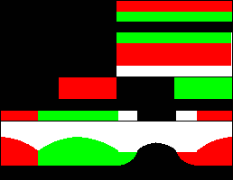
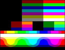
World System Teletext Level 1 (1976) uses a 3-bit RGB, 8-color palette. Teletext has 40×25 characters per page of which the first row is reserved for a page header. Every character cell has a background color and a text color. These attributes along with others are set through control codes which each occupy one character position. Graphics characters consisting of 2×3 cells can used following a graphics color attribute. Up to a maximum of 72×69 blocky pixels can be used on a page.
Simulated image
BBC Micro
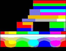
BBC Micro has 8 display modes, with resolutions like 640×256 (max. 2 colors), 320×256 (max. 4 colors) and 160×256 (max. 16 logical colors). No display modes have cell attribute clashes. The palette available has only 8 physical colors, plus a further 8 flashing colors (each being one of the eight non-flashing colors alternating with its physical complement every second), and the display modes can have 16, 4 or 2 simultaneous colors.
Simulated image
BBC Micro display modes
Mode 0 (640 × 256, 2 colors)
Mode 1 (320 × 256, 4 colors)
Mode 2 (160 × 256, 8 colors)
Mode 4 (320 × 256, 2 colors)
Mode 5 (160 × 256, 4 colors)
Mode 8 (80 × 256, 8 colors)
Sinclair QL (Sinclair Quantum Leap)
On the Sinclair QL two video modes were available, 256×256 pixels with 8 RGB colors and per-pixel flashing, or 512×256 pixels with four colors: black, red, green and white. The supported colors could be stippled in 2×2 blocks to simulate up to 256 colors, an effect which did not copy reliably on a TV, especially over an RF connection. Pixel aspect ratio was not square, with resulting image proportions close to 4.4:3, making the image extend into the horizontal overscan area of a CRT TV.
256x256 mode
512x256 mode
Simulated images (aspect ratio corrected)
Simulated images (original pixel size)
256×256
512×256
black
black
blue
red
red
magenta
green
green
cyan
yellow
white
white
PC-8000 series
The NEC PC-8000 was capable of displaying graphics with a resolution of 160x100 pixels and 8 colors.
4-bit RGBI palettes
The 4-bit RGBI palette is similar to the 3-bit RGB palette but adds one bit for intensity. This allows each of the colors of the 3-bit palette to have a variant (on most machines dark or bright, but saturated or unsaturated was also possible) potentially giving a total of 23×2 == 16 colors. Some implementations had only 15 effective colors due to the "dark" and "bright" variations of black being displayed identically. Others generated a grey tone or a different color.
This 4-bit RGBI schema is used in several platforms with variations, so the table given below is a simple reference for the palette richness, and not an actual implemented palette. For this reason, no numbers are assigned to each color, and color order is arbitrary.
Thomson MO5 and TO7 (with spatial constraints - only 2 colours for each group of 8x1 pixels)
Specific details about implementation and actual graphical capabilities of specific systems, are listed on the next sub-sections.
ZX Spectrum
The ZX Spectrum (and compatible) computers use a variation of the 4-bit RGBI palette philosophy. This results in each of the colors of the 3-bit palette to have a basic and bright variant, with the exception of black. This was accomplished by having a maximum voltage level for the bright variant, and a lower voltage level for the basic variant. Due to this, black is the same in both variants.
The attribute byte associated with every 8×8 pixel cell comprises (from LSB to MSB): three bits for the background color; three bits for the foreground color; one bit for the bright variant for both, and one bit for the flashing effect (alternate foreground and background colors every 0.32 seconds). Thus the colors are not independently selectable as indices of a true palette (there are not color numbers 8 to 15, and the bright bit affects both colors within a cell). However, within a single set of 8 colors the BRG order of bits means that the colors appear in increasing order of brightness on a monochrome display.[4]
The color number (0 to 7) can be employed with the following BASIC statements to choose:
BORDER n, the color for the surrounding area outside the pixel graphical area. This cannot use the bright variants.
PAPER n, the background (pixel bit value of 0) color for an 8×8 pixel cell.
INK n, the foreground (pixel bit value of 1) color for an 8×8 pixel cell.
And a value of 0 or 1 with the following statements to choose:
BRIGHT n, sets the bright bit for both foreground and background colors in an 8×8 pixel cell.
FLASH n, sets the bit that controls the flashing effect in an 8×8 pixel cell.
Colours simulated as sRGB assume non-bright as 85% voltage (0.55 V) and bright as 100% (0.65 V).[5] Each ZX Spectrum model used different voltages, so the colors shown are only approximate.
IBM PC/XT and compatible systems
The original IBM PC launched in 1981 features an Intel 8088CPU which has 8-bit data bus technology, though internally the CPU has a fully 16-bit architecture. It was offered with a Monochrome Display Adapter (MDA) or a Color Graphics Adapter (CGA). The MDA is a text mode-only display adapter, without any graphic ability beyond using the built-in code page 437 character set (which includes half-block and line-drawing characters), and employed an original IBM green monochrome monitor; only black, green and intensified green could be seen on its screen.[citation needed] Then, only the CGA had true graphic modes.
The IBM PC XT model, which succeeded the original PC in 1983, has an identical architecture and CPU to its predecessor, only with more expansion slots and a hard disk equipped as standard. The same two video cards, the MDA and the CGA, remained available for the PC XT, and no upgraded video hardware was offered by IBM until the EGA, which followed the introduction of the IBM Personal Computer/AT, with its full 16-bit bus design, in 1984.
CGA
The Color Graphics Adapter (CGA) outputs what IBM called "digital RGB"[6] (that is, the R, G, B (and I) signals from the graphics card to the monitor can each only have two states: on or off).
CGA supports a maximum of 16 colors. However, its 320×200 graphics mode is restricted to fixed palettes containing only four colors, and the 640×200 graphic mode is only two colors. 16 simultaneous colors are only available in text mode or the "tweaked text" 160×100 mode.
The CGA RGBI palette is a variant of the 4-bit RGBI schema, arranged internally like this:.
CGA palette internal bit arrangement (4-bit RGBI)[7]
Color
I
R
G
B
Color
I
R
G
B
Black
0
0
0
0
Gray 2
1
0
0
0
Blue
0
0
0
1
Light Blue
1
0
0
1
Green
0
0
1
0
Light Green
1
0
1
0
Cyan
0
0
1
1
Light Cyan
1
0
1
1
Red
0
1
0
0
Light Red
1
1
0
0
Magenta
0
1
0
1
Light Magenta
1
1
0
1
Yellow / Brown
0
1
1
0
Light Yellow
1
1
1
0
Gray 1
0
1
1
1
White
1
1
1
1
Although the RGBI signals each have only two states, the CGA color monitor (usually mentioned as RGB monitor) decodes them as four level RGB signals. Darker colors are the basic RGB 2nd level signals except for brown, which is dark yellow with the level for the green component halved (1st level). Brighter colors are made by adding a uniform intensity one-level signal to every RGB signal of the dark ones, reaching the 3rd level (except dark gray which reaches only the 1st level), and in this case yellow is produced as if the brown were ordinary dark yellow.
The resulting displayed colors on RGB monitors are shown below:
0 — black
8 — high gray
1 — low blue
9 — high blue
2 — low green
10 — high green
3 — low cyan
11 — high cyan
4 — low red
12 — high red
5 — low magenta
13 — high magenta
6 — low yellow (brown)
14 — high yellow
7 — low gray
15 — white
A few earlier non-IBM compatible CGA monitors lack the circuitry to decode color numbers as of four levels internally, and they cannot show brown and dark gray. The above palette is displayed in such monitors as follows:
0 — black
8 — black*
1 — low blue
9 — high blue
2 — low green
10 — high green
3 — low cyan
11 — high cyan
4 — low red
12 — high red
5 — low magenta
13 — high magenta
6 — low yellow* (brown)
14 — high yellow
7 — light gray* (gray)
15 — white
16-color palette modes
The only full 16-color BIOS modes of the CGA are the text mode 0 (40×25) and mode 2 (80×25). Disabling the flashing attribute effect and using the IBM 437 codepage block characters 220 (DCh) ▄ (bottom half) or 223 (DFh) ▀ (upper half), the mode 2 screen buffer provides an 80×50 quasi-graphic mode.
Also, a tweak mode can be set in the CGA to give an extra, non-standard 160×100 pixels 16-color graphic mode.
In the 320×200 graphics mode, every pixel has two bits. A value of 0 is always a selectable background-plus-border color (with the same register and/or BIOS call used for the foreground color in the 640×200 graphic mode; black by default), and the three remaining values 1 to 3 are indices to one of the predefined color palette entries.
The selection of a palette is a bit complex. There are two BIOS 320×200 CGA graphics modes: modes 4 and 5. Mode 4 has the composite color burst output enabled (in the Mode Control Register at I/O address 3D8H, bit 2 is cleared), and mode 5 has it disabled (the same bit 2 is set). Mode 5 is intended mainly for a monochrome composite video monitor, but because of a specific intentional feature of the CGA hardware, it also has a different palette for an RGBI color monitor. For mode 4, two palettes can be chosen: green/red/brown and cyan/magenta/white; the difference is the absence or presence of the blue signal in all three colors. (The palette is selected with bit 5 of the Color-Select Register at I/O address 3D9h, where the bit value 1 selects the cyan/magenta/white palette [a/k/a "palette #1" because it is the BIOS default] and 0 selects the green/red/brown palette [a/k/a "palette #2"]. This bit can be set using BIOS INT 10h function 0Bh, subfunction 1.) The palette for BIOS video mode 5 is always cyan/red/white: blue is always on, and red and green each are controlled directly by one of the two bits of the pixel color value. For each of these three palette options, a low or high intensity palette can be chosen with bit 4 of the aforementioned Color-Select Register: a value of 0 means low intensity and 1 means high intensity. (No BIOS call exists to switch between the two intensity modes.) The selected intensity setting simply controls the "I" output signal to the RGBI monitor for all colors in the palette. As a result, the green-red-brown palette appears as bright-green/bright-red/yellow when high intensity is selected. The combination of color-burst enable/disable selection, palette selection, and intensity selection yields a total of 6 different possible palettes for CGA 320×200 graphics.
Mode 4, palette #1, low intensity
0 — [user-defined]
1 — cyan
2 — magenta
3 — light grey
The sixteen combinations with the background color are:
0
1
_
0
1
_
0
1
_
0
1
*
0
1
_
0
1
*
0
1
_
0
1
*
2
3
_
2
3
_
2
3
_
2
3
_
2
3
_
2
3
_
2
3
_
2
3
_
0
1
_
0
1
_
0
1
_
0
1
_
0
1
_
0
1
_
0
1
_
0
1
_
2
3
_
2
3
_
2
3
_
2
3
_
2
3
_
2
3
_
2
3
_
2
3
_
(*) Useless due to the duplication of one of the colors.
Mode 4, palette #1, high intensity
0 — [user-defined]
1 — bright cyan
2 — bright magenta
3 — bright white
The sixteen combinations with the background color are:
0
1
_
0
1
_
0
1
_
0
1
_
0
1
_
0
1
_
0
1
_
0
1
_
2
3
_
2
3
_
2
3
_
2
3
_
2
3
_
2
3
_
2
3
_
2
3
_
0
1
_
0
1
_
0
1
_
0
1
*
0
1
_
0
1
*
0
1
_
0
1
*
2
3
_
2
3
_
2
3
_
2
3
_
2
3
_
2
3
_
2
3
_
2
3
_
(*) Useless due to the duplication of one of the colors.
Mode 4, palette #2, low intensity
0 — [user-defined]
1 — green
2 — red
3 — brown
The sixteen combinations with the background color are:
0
1
_
0
1
_
0
1
*
0
1
_
0
1
*
0
1
_
0
1
*
0
1
_
2
3
_
2
3
_
2
3
_
2
3
_
2
3
_
2
3
_
2
3
_
2
3
_
0
1
_
0
1
_
0
1
_
0
1
_
0
1
_
0
1
_
0
1
_
0
1
_
2
3
_
2
3
_
2
3
_
2
3
_
2
3
_
2
3
_
2
3
_
2
3
_
(*) Useless due to the duplication of one of the colors.
Mode 4, palette #2, high intensity
0 — [user-defined]
1 — bright green
2 — bright red
3 — yellow
The sixteen combinations with the background color are:
0
1
_
0
1
_
0
1
_
0
1
_
0
1
_
0
1
_
0
1
_
0
1
_
2
3
_
2
3
_
2
3
_
2
3
_
2
3
_
2
3
_
2
3
_
2
3
_
0
1
_
0
1
_
0
1
*
0
1
_
0
1
*
0
1
_
0
1
*
0
1
_
2
3
_
2
3
_
2
3
_
2
3
_
2
3
_
2
3
_
2
3
_
2
3
_
(*) Useless due to the duplication of one of the colors.
Mode 5, low intensity
0 — [user-defined]
1 — cyan
2 — red
3 — light grey
The sixteen combinations with the background color are:
0
1
_
0
1
_
0
1
_
0
1
*
0
1
*
0
1
_
0
1
_
0
1
*
2
3
_
2
3
_
2
3
_
2
3
_
2
3
_
2
3
_
2
3
_
2
3
_
0
1
_
0
1
_
0
1
_
0
1
_
0
1
_
0
1
_
0
1
_
0
1
_
2
3
_
2
3
_
2
3
_
2
3
_
2
3
_
2
3
_
2
3
_
2
3
_
(*) Useless due to the duplication of one of the colors.
Mode 5, high intensity
0 — [user-defined]
1 — bright cyan
2 — bright red
3 — white
The sixteen combinations with the background color are:
0
1
_
0
1
_
0
1
_
0
1
_
0
1
_
0
1
_
0
1
_
0
1
_
2
3
_
2
3
_
2
3
_
2
3
_
2
3
_
2
3
_
2
3
_
2
3
_
0
1
_
0
1
_
0
1
_
0
1
*
0
1
*
0
1
_
0
1
_
0
1
*
2
3
_
2
3
_
2
3
_
2
3
_
2
3
_
2
3
_
2
3
_
2
3
_
(*) Useless due to the duplication of one of the colors.
When viewed in a monochrome composite monitor, the mode 5 palettes above are shown as a (more or less brighter) 2-bit grayscale palette:
2-color palette mode
In the 640×200 graphic mode (BIOS mode number 6), every pixel has only a single bit. The foreground color can be set, with the default being white.
2-color
2-color comparison image
0 — black
1 — [user-defined]
The sixteen combinations are:
0
1
_
0
1
_
0
1
_
0
1
_
0
1
_
0
1
_
0
1
_
0
1
_
0
1
_
0
1
_
0
1
_
0
1
_
0
1
_
0
1
_
0
1
_
0
1
_
PCjr and Tandy 1000 series
The IBM PCjr features a "CGA Plus" video subsystem, consisting mainly of a 6845 CRTC and an LSI video chip known as the "Video Gate Array", that can show all 16 CGA colors simultaneously on screen in the extended low-res graphic modes. The near-compatible Tandy 1000 series features almost 100% PCjr-compatible video hardware implemented in a Tandy proprietary chip. This graphics adapter is better known by the name Tandy Graphics Adapter, because the PCjr was short-lived but the Tandy 1000 line was quite popular for many years. The video mode capabilities of early-model Tandy 1000 computers are exactly the same as the PCjr's. (Later Tandy 1000 models featured "Tandy Video II" hardware which added a 640x200 16-color mode but surrendered PCjr hardware register-compatibility for CGA register-compatibility.)
The PCjr adds three video modes to the CGA mode set: 160×200 16-color "low-resolution" graphics, 320×200 16-color "medium-resolution" graphics, and 640×200 4-color "high-resolution" graphics. All PCjr/Tandy 1000 graphics modes can reassign any color index to any palette entry, allowing free selection of all palette colors in modes with fewer than 16 colors (including the plain CGA modes) and enabling color cycling effects in all modes. The PCjr also offers a graphics blink function which causes 8 colors to alternate between the low and high halves of the 16-color palette at the text blink rate. (A PCjr must be upgraded with a PCjr-specific internal 64 KB memory expansion card in order to use the latter two of these modes or any 80-column text mode. Tandy 1000 base models can use all video modes.)
0
1
2
3
4
5
6
7
8
9
10
11
12
13
14
15
Thomson
For Thomson computers, a popular brand in France, the most common display modes are 320×200, with 8×1 attribute cells with 2 colors. Here the intensity byte affects saturation and not only brightness variations.
Thomson MO5
The Thomson MO5 generated graphics based on a EFGJ03L (or MA4Q-1200) gate array[8] capable of 40×25 text display and a resolution of 320 x 200 pixels with 16 colours (subject to proximity constraints - only two colors for a 8x1 pixel area).[9]
The colour palette has 8 basic RGB colours with an intensity bit (called P for "Pastel") that controlled saturation ("saturated" or "pastel").[10][11] In memory, the bit order was PBGR. The desaturated colours were obtained by mixing of the original RGB components within the video hardware. This is done by a PROM circuit, where a two bit mask controls colour mixing ratios of 0%, 33%, 66% and 100% of the saturated hue.[10] This approach allows the display of Orange instead of "desaturated white", and Gray instead of "desaturated black".
According to the values specified on the computer's technical manual (“Manuel Technique du MO5”,[10] pg. 11 & 19), the hardware palette was:[11]
Displayed colors are only approximate due to different transfer and color spaces used on web pages (sRGB) and analog video (BT.601)
Actual colour on emulators and later models seems to have been tweaked, with normal Blue and Red being fully saturated.[12]
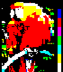
Simulated image
Color test chart
Thomson TO7/70
The Thomson TO7/70 graphics were similar to the Thomson MO5[13] and generated by a Motorola MCA1300 gate array.[14] capable of 40×25 text display and a resolution of 320 x 200 pixels with 16 colours (limited by 8x1 pixel colour attribute areas).[15][16] The colour palette is 4-bit RGBI, with 8 basic RGB colours and a intensity bit (called P for "Pastel") that controlled saturation ("saturated" or "pastel").[10][11]
Fixed color palette 1 (similar to MO5)
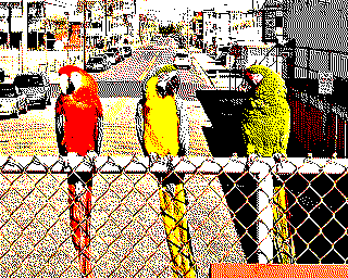
Sample image
Color test chart
0x0 K
0x1 B
0x2 R
0x3 M
0x4 G
0x5 C
0x6 Y
0x7 W
0x8
0x9
0xA
0xB
0xC
0xD
0xE
0xF
Fixed color palette 2
0x0
0x1
0x2
0x3
0x4
0x5
0x6
0x7
0x8
0x9
0xA
0xB
0xC
0xD
0xE
0xF
Fixed color palette 3
Example of 16 fixed color palette 3
0x0
0x1
0x2
0x3
0x4
0x5
0x6
0x7
0x8
0x9
0xA
0xB
0xC
0xD
0xE
0xF
Mattel Aquarius
The Mattel Aquarius computer has a text mode with 40×24 characters, that can be used as a semigraphic 80×72 low resolution graphics mode. There are spatial constraints ("attribute" areas) for different colors, consisting of 2x3 pixel groups.
The machine uses a TEA1002 graphic chip, and there are three bits for the RGB components (generating 8 primary colors at full saturation but 75% luminance - similar to the EBU colour bars) and an intensity bit that controls a variation of the base color (a 75% luminance decrease for white, creating gray; a 50% chroma saturation decrease for the RGB primary colors).[17][18][19]
An alternate configuration of the chip allows it to output 95% luminance color bars - similar to BBC colour bars, more suited for usage in teletext decoders.[19]
3 level RGB palettes
Amstrad CPC series
The AmstradCPC 464/664/6128 series of computers generates the available palette with 3 levels (not bits) for every RGB primary. Thus, there are 27 different RGB combinations, from which 16 can be simultaneously displayed in low resolution mode, four in medium resolution mode and two in high resolution mode.[20]
Simulations of actual images on the Amstrad's color monitor in each of the modes (160×200x16 colors; 320×200x4 colors and 640×200x2 colors) follows. A cheaper green monochrome display was also available from the manufacturer; in this case, the colors are viewed as a 16-tone green scale, as shown in the last simulated image, as it interprets the overall brightness of the full color signal, instead of only considering the green intensity as might, e.g., the Philips CM8833 line.
2 colors
4 colors
16 colors
16-tone green scale
0 – Black (5)
1 – Dark blue (0,14)
2 – Blue (6)
3 – Dark red
4 – Dark magenta
5 – Violet
6 – Red (3)
7 – Magenta-red
8 – Magenta (7)
9 – Dark green
10 – Dark cyan (8)
11 – Cyan-blue (15)
12 – Dark yellow (brown) (9)
13 – Grey
14 – Light blue (10)
15 – Orange
16 – Pink (11, 15)
17 – Light magenta
18 – Green (12)
19 – Cyan-green
20 – Cyan (2)
21 – Yellow-green
22 – Light green (13)
23 – Light cyan
24 – Yellow (1, 14)
25 – Light yellow
26 – White (4)
The number in parentheses means the primary ink number for the Locomotive BASIC PEN, PAPER and INK statements (that is, "(1)" means ink #1 defaults to this color). Inks can also have a secondary color number, meaning they flash between two colors. By default, ink #14 alternates between colors 1 and 24 (blue and bright yellow) and ink #15 alternates between colors 11 and 16 (cyan-blue and pink). In addition, the paper defaults to ink #0 and the pen to ink #1, meaning yellow text on a dark blue background.
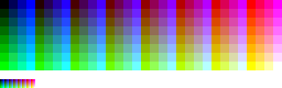
8-bit RGB palettes
The 8-bit RGB palettes (also known as 3-3-2 bit RGB) use 3 bits for each of the red and green color components, and 2 bits for the blue component, due to the lesser sensitivity of the common human eye to this primary color. This results in an 8×8×4 = 256-color palette as follows:
Red
#000000
#240000
#490000
#6D0000
#920000
#B60000
#DB0000
#FF0000
Green
#000000
#002400
#004900
#006D00
#009200
#00B600
#00DB00
#00FF00
Blue
#000000
#000055
#0000AA
#0000FF
Tiki 100
The Tiki 100 uses an 8-bit RGB palette (also described as 3-3-2 bit RGB), with 3 bits for each of the red and green color components, and 2 bits for the blue component. It supports 3 different resolutions with 256, 512 or 1024 by 256 pixels and 16, 4, or 2 colors respectively (freely selectable from the full 256-color palette).
Enterprise
The Enterprise computer has five graphics modes: 40- and 80-column text modes, Lo-Res and Hi-Res bit mapped graphics, and attribute graphics. Bit mapped graphics modes allow selection between displays of 2, 4,16 or 256 colors (from a 3-3-2 bit RGB palette), but horizontal resolution decreases as color depth increases.
Interlaced and non-interlaced modes are available. The maximum resolution is 640×512 pixels interlaced, or 640×256 pixels non-interlaced. These resolutions permit only a 2-colour display.
A 256-colour display has a maximum resolution of 80×256. The attribute graphics mode provides a 320×256 pixel resolution with 16 colors, selectable from a palette of 256.
Multiple pages can be displayed simultaneously on the screen, even if their graphics modes are different. Each page has its own palette, which allows more colors to be displayed onscreen simultaneously. The page height can be larger than the screen or the window it is displayed on. Each page is connected to a channel of the EXOS operating system, so it is possible to write on a hidden page.
MSX2
On the MSX2 screen mode 8 is a high-resolution 256×212-pixel mode with an 8-bit color depth, giving a palette of 256 colors (Fixed RGB mode of the Yamaha V9938 video chip).[21] From the MSB to LSB, there are three green bits, three red bits, and two blue bits. This mode uses half of the available colors overall, and can be considered a palette in its own right.
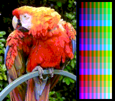
9-bit RGB palettes
The MSX2 series features a Yamaha V9938 video chip, which manages a 9-bit RGB palette (512 colors in Paletted RGB mode) and has some extended graphic modes. Although its graphical capabilities are similar, or even better than of those of 16-bitpersonal computers, MSX2 and MSX2+ (see below) are pure 8-bit machines.
Screen mode 6 is a 512×212-pixel mode with a 4-color palette chosen from the available 512 colors. Screen modes 5 and 7 are high-resolution 256×212-pixel and 512×212-pixel modes, respectively, with a 16-color palette chosen from the available 512 colors. Each pixel can be any of the 16 selected colors.
4-color screen mode 6
16-color screen mode 5
15-bit RGB palettes
MSX2+
The MSX2+ series (released in 1988) features a Yamaha V9958 video chip which manages a 15-bit RGB palette internally encoded in YJK (up to 19,268 different colors from the 32,768 theoretically possible)[22] and has additional screen modes. Although its graphical capabilities are similar, or even better than of those of 16-bitpersonal computers, MSX2 (see above) and MSX2+ are pure 8-bit machines. YJK color encoding can be viewed as a lossy compression technique; in the RGB to YJK conversion, the average red and green levels are preserved, but blue is subsampled. As a result of every four pixels sharing a chroma value, in mode 12 it is not possible to have vertical lines of a single color. This is only possible in modes 10 and 11 due to the additional 16-color direct palette. This can be used to mix 16 indexed colors with a rich colorful background, in what can be considered a primitive video overlay technique.
Screen modes 10 & 11 – 12,499 YJK colors plus a 16-color palette. In this mode, the YJK technique encodes 16 levels of luminance into the four LSBs of each pixel and 64 levels of chroma, from −32 to +31, shared across every four consecutive pixels and stored in the three higher bits of the four pixels. If the fifth bit of the pixel is set, then the lower four bits of the pixel points to an index in the 16-color palette; otherwise, they specify the YJK luminance level of the pixel.
Screen mode 12 is similar to modes 10 and 11, but uses five bits to encode 32 levels of luminance for every pixel, thus it does not use an additional palette and, with YJK encoding, 19,268 different colors can be displayed simultaneously with 8-bit color depth.
Screen mode 10 & 11
Screen mode 12
18-bit RGB palettes
(Learn how and when to remove this message)
FM-77 AV 40
Fujitsu's FM-77 AV 40, released in 1986, uses an 18-bit RGB palette. Any 64,000 out of 262,144 colors can be displayed simultaneously at the 320×200 resolution, or 8 out of 262,144 colors at the 640×400 resolution.
Composite video palettes
This section covers systems that generate color directly as composite video, closely related with display on analog CRT TVs. Many of the colors are non-standard and outside of RGB gamut, and would only display properly on NTSC hardware. Due to the varying ways of converting a composite signal to sRGB (the standard for internet images), images in this section will be inconsistent with each other in color until further notice.
Atari 8-bit computers
Early models of the Atari 400 and 800 use a palette of 128 colors, using 4 bits for chrominance and 3 for luminance. Screen modes may vary from 320×192 (384x240 with overscan) to 40×24, using 2 or 4 simultaneous colors, or 80×192 (96x240 with overscan) using 16 colors. After 2 years (late 1981) the CTIA graphics chip was replaced with the GTIA chip increasing the palette to 256 colors (CTIA and GTIA).
The ANTIC chip has an instruction set to run programs (called display lists) which permits many more colors on the screen at once. There are a number of possible software-driven graphics modes.
The 40x48 pixel lo-res mode allowed 15 different colors plus a duplicate gray.[25]
Number — name
Y
I
Q
Number — name
Y
I
Q
0 — black
0
0
0
8 — brown*
0.25
0.5
-0.5
1 — red
0.25
0.5
0.5
9 — orange
0.5
1
0
2 — dark blue
0.25
-0.5
0.5
10 — gray
0.5
0
0
3 — purple
0.5
0
1
11 — pink
0.75
0.5
0.5
4 — dark green
0.25
-0.5
-0.5
12 — bright green
0.5
0
-1
5 — gray
0.5
0
0
13 — yellow
0.75
0.5
-0.5
6 — blue-cyan
0.5
-1
0
14 — cyan
0.75
-0.5
0.5
7 — light blue
0.75
-0.5
0.5
15 — white
1
0
0
Notes: Italic text and three asterisks (***) denotes colors outside of RGBgamut.
High-res mode palette
The majority of Apple graphic applications used the hi-res mode, which had 280×192 pixels (effectively 140x192 on a color monitor). The hi-res mode allowed six colors: black, white, blue, orange, green and purple.
High bit
Pixel pair
Number — Name
Y
I
Q
0
00
0 — black
0
0
0
0
01
1 — purple
0.5
1
1
0
10
2 — green
0.5
−1
−1
0
11
3 — white
1
0
0
1
00
4 — black
0
0
0
1
01
5 — blue
0.5
1
−1
1
10
6 — orange
0.5
−1
1
1
11
7 — white
1
0
0
Systems based on MOS Technology chips
For all the following computers from Commodore, the U and V coordinates for the composite video colors are always the cosine and the sine, respectively, of angles multiple of 22.5 degrees (i.e. a quarter of 90°), as the engineers were inspired by the NTSCcolor wheel, a radial way to figure out the U and V coordinates of points equidistant from the center of the chroma plane, the gray. Consumers in Europe (which uses PAL) considered the Commodore colors to be more "washed out" and less vivid than those provided by computers such as the ZX Spectrum.[26][27][28]
The VIC-20 lacks any true graphic mode, but a 22×11 text mode with 200 definable characters of 8×16 bits each arranged as a matrix of 20×10 characters is usually used instead, giving a 3:2(NTSC)/5:3(PAL) pixel aspect ratio, 160×160 pixels, 8-color "high-res mode" or a 3:1(NTSC)/10:3(PAL) pixel aspect ratio, 80×160 pixels, 10-color "multicolor mode".
VIC-20 palette
In the 8-color high-res mode, every 8×8 pixels can have the background color (shared for the entire screen) or a free foreground color, both selectable among the first eight colors of the palette. In the 10-color multicolor mode, a single pixel of every 4×8 block (a character cell) may have any of four colors: the background color, the auxiliary color (both shared for the entire screen and selectable among the entire palette), the same color as the overscan border (also a shared color) or a free foreground color, both selectable among the first eight colors of the palette.
Simulated images
Multicolor mode
High-res mode
On some models of the system, there are nine levels of luminance:
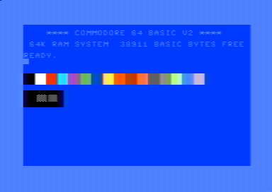
The MOS Technology VIC-II is used in the Commodore 64 (and Commodore 128 in 40-column mode), and features a 16-color YPbPrcomposite video palette.[30] This palette is largely based on that of the VIC, but it substitutes three colors by three levels of gray. When displayed over an analog NTSC composite video output, the actual resulting colors are more vivid.
The Commodore 64 has two graphic modes: Multicolor and High Resolution.
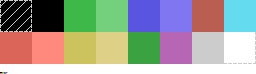
In the Multicolor 160×200, 16-color mode, every cell of 4×8, 2:1 aspect ratio pixels can have one of four colors: one shared with the entire screen, the two background and foreground colors of the corresponding text mode character, and one more color also stored in the color RAM area, all of them freely selectable among the entire palette.
In the High Resolution 320×200, 16-color mode, every cell of 8×8 pixels can have one of the two background and foreground colors of the correspondent text mode character, both freely selectable among the entire palette.
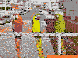
Simulated images
16-color multicolor mode
16-color High-res mode
On most models of the Commodore 64, there are nine levels of luminance:
The MOS Technology TED was used in the Commodore 16 and Commodore Plus/4. It has a palette of 121 YPbPrcomposite video colors[32] consisting of sixteen hues (including black and white) at eight luminance levels. Black is the same color at every luminance level, so there are not 128 different colors. On the Commodore Plus/4, twelve colors formed a "default" palette of sorts accessible through keyboard shortcuts;[33] these colors are underlined in the table below (RGB converted colors at a saturation level of 34%).
The Commodore 16 and Commodore Plus/4 have two graphic modes very similar to those of the Commodore 64: Multicolor and High Resolution.
In the Multicolor 160×200, 121-color mode, every cell of 4×8, 2:1 aspect ratio pixels can have one of four colors: two shared with the entire screen and the two background and foreground colors of the correspondent text mode character, all of them freely selectable among the entire 121-color palette (hue 0 to 15 and luminance 0 to 7 are set individually for any of them).
In the High Resolution 320×200, 121-color mode, every cell of 8×8 pixels can have one of the two background and foreground colors of the corresponding text mode character, both freely selectable among the entire 121-color palette (again setting both the hue and the luminance).
The TMS9918 chip which uses a proprietary 15-color YUVcomposite video palette encoded palette[34] plus a transparent color, intended to be used by the hardware sprites and simple video overlay. When used as an ordinary background color, it is rendered using the same color as the screen border.
TMS9918 YUV composite video palette
Number — name
Y
U
V
0 — transparent
N/A
N/A
N/A
1 — black
0.00
0.000
0.000
2 — medium green
0.53
−0.509
−0.755
3 — light green
0.67
−0.377
−0.566
4 — dark blue
0.40
1.000
−0.132
5 — light blue
0.53
0.868
−0.075
6 — dark red
0.47
−0.321
0.679
7 — cyan
0.73
0.434
−0.887
8 — medium red
0.53
−0.377
0.868
9 — (light red)
0.67
−0.377
0.868
10 — dark yellow
0.73
−0.755
0.189
11 — light yellow
0.80
−0.566
0.189
12 — dark green
0.47
−0.453
−0.642
13 — magenta
0.53
0.377
0.491
14 — gray
0.80
0.000
0.000
15 — white
1.00
0.00
0.000
Note: The colors inside the parentheses are out of RGB gamut.
MSX
The MSX series has two graphic modes. The MSX BASIC Screen 3 mode is a low-resolution mode with 15 colors, in which every pixel can be any of the 15 available colors. Screen mode 2 is a 256×192 high-resolution mode with 15 colors, in which each of every eight consecutive pixels can only use 2 colors.
Color is generated by the combination of three signals, (luminance) with 6 possible levels, and (chroma) with 3 possible levels, based on the YPbPrcolorspace, and then converted for output into a NTSC analog signal.
The following table shows the signal values used:[35]
Color
Green
0.54
1.0
1.0
Yellow
0.42
1.0
1.5
Blue
0.72
2.0
1.5
Red
0.72
1.5
2.0
Buff
0.42
1.5
1.5
Cyan
0.54
1.5
1.5
Magenta
0.54
2.0
2.0
Orange
0.54
1.0
2.0
Black
0.72
1.5
1.5
Dark Green
0.72
1.0
1.0
Dark Orange
0.72
1.0
2.0
TRS-80 Color Computer
The TRS-80 Color Computer is capable of displaying text and graphics contained within a roughly square display matrix 256 pixels wide by 192 lines high. The hardware palette has 9 colors: black, green, yellow, blue, red, buff (almost-but-not-quite white), cyan, magenta, and orange.[36]
All colors are available in text modes. In color modes (64×64, 128×64, 128×96, and 128×192) two four color palettes are available: a green border with the colors green, yellow, red, and blue; a white border with the colors white, cyan, magenta, and orange.
Text Mode (9 colors)
Color mode (4 colors)
Color mode (alternate palette)
NEC PC-6000 series
Similar to other computers using the same video chip, the NEC PC-6000 series had four screen modes:
32x16 characters with 4 colors
64x48 pixel graphics with 9 colors
128x192 graphics with 4 colors
256x192 graphics with 2 colors (green, white)
Other palettes
Tandy Color Computer 3
The Tandy Color Computer 3 could display all of the modes of the Tandy Color Computer 1 and 2 / TRS-80 Color Computer, except the Semigraphics modes. Taking the place of the graphics and memory hardware of the previous machines is an application-specific integrated circuit called (officially) the Advanced Color Video Chip (ACVC) or (unofficially) the Graphics Interrupt Memory Enhancer (GIME).
This chip allowed resolutions of 320x192x4, 320x192x16, 640x192x2, and 640x192x4 from a palette of 64 colors.[37]
There are two palette modes - RGB (3 levels of intensity plus white, black and two grays) and Composite (total of 64 colors; 16 distinct chroma values with 4 levels of luminance).[38][39]
Tandy Color Computer 3 composite palette examples
SAM Coupé
The 128 color master palette used by the SAM Coupé is produced via a unique method — it effectively contains 2 groups of 64 "RGB" colors of mildly different intensity, and ultimately derived from a 512 color space.[40] The closest equivalent in more popular and well-known machines would be the Commodore Amiga's 64-color "Extra Half-Brite" mode (with 32 explicitly set colors using 5 bitplanes, which are displayed with full or half brightness depending on the bit setting of a 6th plane).
Two bits are used for each of Red, Green and Blue and give a similar result to a normal 6-bit RGB palette (as seen with the IBM EGA or Sega Master System); the seventh bit encodes for "brightness", which has a similar but more subtle effect to the Spectrum, increasing the output of all three channels by half the intensity of the lower bits of the main six (in this way, it does make a genuine 128 colors — rather than 127 colors with "two blacks" and only a 7-level grayscale).
The layout of the byte that encodes each color is complicated and appears like a Spectrum color nybble transferred to a full byte's width, and an extra RGB bit-triplet then prefixed to it, with the MSB left unused.
SAM Coupé color palette value bits
Bit 7
Bit 6
Bit 5
Bit 4
Bit 3
Bit 2
Bit 1
Bit 0
-
Green 1
Red 1
Blue 1
Half-Bright
Green 0
Red 0
Blue 0
Resulting color palette:
SAM Coupé color palette example images
SAM Coupé color palette and bitmask
0x00
0x01
0x02
0x03
0x04
0x05
0x06
0x07
0x08
0x09
0x0A
0x0B
0x0C
0x0D
0x0E
0x0F
0x10
0x11
0x12
0x13
0x14
0x15
0x16
0x17
0x18
0x19
0x1A
0x1B
0x1C
0x1D
0x1E
0x1F
0x20
0x21
0x22
0x23
0x24
0x25
0x26
0x27
0x28
0x29
0x2A
0x2B
0x2C
0x2D
0x2E
0x2F
0x30
0x31
0x32
0x33
0x34
0x35
0x36
0x37
0x38
0x39
0x3A
0x3B
0x3C
0x3D
0x3E
0x3F
0x40
0x41
0x42
0x43
0x44
0x45
0x46
0x47
0x48
0x49
0x4A
0x4B
0x4C
0x4D
0x4E
0x4F
0x50
0x51
0x52
0x53
0x54
0x55
0x56
0x57
0x58
0x59
0x5A
0x5B
0x5C
0x5D
0x5E
0x5F
0x60
0x61
0x62
0x63
0x64
0x65
0x66
0x67
0x68
0x69
0x6A
0x6B
0x6C
0x6D
0x6E
0x6F
0x70
0x71
0x72
0x73
0x74
0x75
0x76
0x77
0x78
0x79
0x7A
0x7B
0x7C
0x7D
0x7E
0x7F
These colors can be used on the four available display modes:[41]
Mode 4 - 256×192 graphics with 16 colours
Mode 3 - 512×192 graphics with 4 colours
Mode 2 - 256×192 graphics with 2 colors (from 16) for each 8-wide block of pixels
Mode 1 - 256×192 graphics with 2 colors (from 16) for each 8x8 block of pixels (matching the display of the ZX Spectrum for backwards compatibility)
SAM Coupé video modes example images
SAM Coupé mode 1 example image
SAM Coupé mode 2 example image
SAM Coupé mode 3 example image
SAM Coupé mode 4 example image
Side-by-side comparison
Since there are many 8-bit computers to compare, a comparison table has been compiled to make comparing the systems easier.
8-bit computer color palettes
Computer(s)
Picture sample(s)
Entire palette(s)
Number of colors on screen
Resolution(s)
Apple II
Hi-res:
Lo-res:
Hi-res:
Lo-res:
6 (high resolution mode), or 16 (low resolution mode)
280x192 in high resolution or 40x48 in low resolution
Atari 8-bit line
Mode 15 (with color interrupts and MCS):
9 colors per scanline on mode 15 via masking the 4 sprites for colors, and interrupts.
Ranges from 320x192, with 1 color, to 80x192 with 9 colors.
Mattel Aquarius
16 colors
40x24 characters
BBC Micro
Ranges from 2 to 8 colors
Ranges from 640x256 to 160x256
Commodore 64
High res mode:
Multicolor mode:
All 16 colors can be present in one screen. However, 4 can be present in one 4 x 8 cell in multicolor mode, and three of those colors must be shared. 2 colors can be present in every 8 x 8 cell in high resolution mode.
320 x 200 in high resolution mode
160 x 200 in multicolor mode
CGA
16 color mode:
4 color modes:
2 color mode:
320×200 graphics mode is restricted to fixed palettes containing only four colors; 640×200 graphic mode is only two colors
^"Spectrum vs C64" match, Italy, 1985 "The blue was simply stunning. The red made the room warm. The magenta was like an exotic icecream. The green was something like freshly rained grass. The cyan was like the ocean's water. The yellow seemed got off from a fluorescent pen. And the white was clean and soft ... The C64 screen first became black (but not too much), then became white (an exaggerated white), then orange, then something like bluish, then a vaguely magenta, then a poor water-greenish, then a bright bluish, then a faded yellow, then a weird brown, and then a light gray... well, all "pastel-like" colours"
^ZX Spectrum vs Commodore 64 – the playground argument settled "you will remember the playground taunts regarding washed out colours, peeks and pokes and the relative lack of software in your local WH Smith"
^ZX Spectrum vs Commodore 64 "the C64 had muddy colours...but whack up the colour saturation of your TV and most of that was alleviated"
^"The 6561 VIC chip". Archived from the original on 2010-04-01. 090420 fpgaarcade.com
^Philip 'Pepto' Timmermann (12 March 2001). "All you ever wanted to know about the colors of the commodore 64". pepto.de.
^"C64 Emulator Palette from my NTSC 1702 - Page 2 - Commodore 64 (C64) Forum". lemon64.com.
^"Commodore Hacking #12 : Talking to TED". Archived from the original on 5 January 2009.
^"Color codes". Archived from the original on 27 September 2007.
^VDP Registers 00h-07h: Basic MSX1/MSX2 Video Registers from "Portar MSX Tech Doc" Archived 2007-11-30 at the Wayback Machine
^"MC6847* datasheet & applicatoin notes - Datasheet Archive". www.datasheetarchive.com. Archived from the original on 2022-07-10. Retrieved 2021-05-15.
^"Color Computer FAQ - CoCopedia - The Tandy/Radio Shack Color Computer Wiki". www.cocopedia.com. Retrieved 25 November 2023.
^Lomont, Chris (July 2006). "Chris Lomont's Color Computer 1/2/3 Hardware Programming" (PDF). www.lomont.org. Archived from the original (PDF) on 2022-06-05. Retrieved 5 May 2020.
^"Coco 3 Graphics". aaronwolfe.com. Retrieved 25 November 2023.
^Cooke, Simon; et al. (1994). "The Graphics Hardware" (PDF). The Unofficial SAM Coupé Technical Manual (sampler edition). Σntropy. pp. 16–20. Retrieved 5 February 2013.